Utility Management
In this window, you can manage your utilities, system codes, and devices within your network. Only roles with the appropriate permission can manage utilities, codes, and devices.
What You Can See and Do in This Window
Click a link to display the related information or step-by-step procedure.
| – | ||
| – | ||
| – | – | |
| – | ||
| – | ||
| – | – | |
| – | – | |
| – | – | |
| – | – | |
| – | – |

Create or Update a Utility
You can create new utilities within your system and update the information for any utility. When you create a utility, you must define the time zone, which is expressed as the difference in time between UTC time (GMT time) and a location's observed time. This UTC offset adjusts for global time zones. The Daylight Saving Time option subtracts an additional hour from the UTC time during the period between March and November, and then adds the hour back when standard time resumes.
- On the Neptune 360 navigation panel, click Device Management under Utility Management.
- On the Utility Management (Device Management) software page, in the Code Management section, click Create, or in the Utility section, click Edit.
The system displays the Create New or Update Utility window.
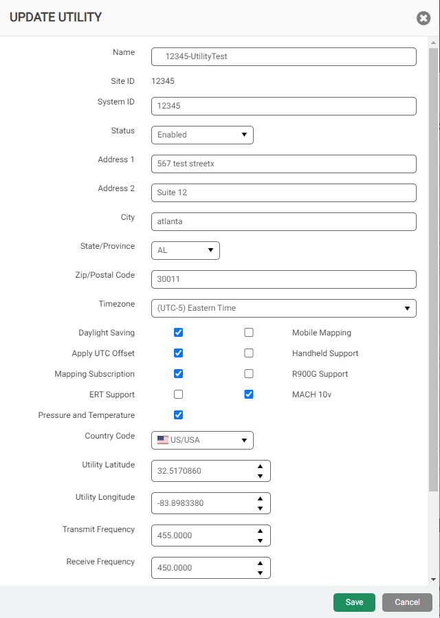
- Select and enter data in the fields as required. At a minimum, complete the required fields outlined in red.
Click unit of measure for additional information about units of measure Neptune 360 uses.
- Click Save to save the changes.
Utility Field Descriptions
The following table describes the fields for each utility that you define or edit.
| Field | Description |
|---|---|
| Address 1 | First address line for the utility. |
| Address 2 | Second address line for the utility. |
| Apply UTC Offset | Indicates whether to apply the UTC Offset. Select this option, unless the utility location is in the UTC time zone. |
| Auto-Complete Days | Only readings within this time frame are used for billing for this utility. The auto-complete readings occur once an hour. The readings include active and inactive accounts. You can change the default of 7 to any number between 0 and 10. |
| Cellular Devices | Indicates whether configurable scheduling is available for utilities that have cellular devices. |
| City | City where the utility is located. |
| Close Route on Export | Close the route after exporting the data. |
| Country Code | Code for the country where the utility is located. |
| Daylight Saving | Indicates whether the utility location observes daylight saving and adjusts the time accordingly. Note that this selection also synchronizes with My360 for the utility. |
| Default Unit of Pressure | Default measurement of pressure for meters within the utility system that includes pressure capability. The Unit of Measure (UDM |
| Default Unit of Temperature | Default measurement of temperature for meters within the utility system that includes temperature capability. The Unit of Measure (UDM |
| Default Unit of Volume | Default measurement of volume for the utility readings. |
| ERT Support | Indicates whether the utility has ERT |
| Fail Import by Line | Indicates whether Neptune 360 allows one or more lines to fail but continues the import, or whether one failed line halts the import. This option selected may impact route management, reporting, and billing exports. |
| Mapping Subscription | Indicates whether geocoding services are enabled for the utility. The default for this option is No. |
| Handheld EULA Accepted | Indicates whether the utility has enabled the End User License Agreement (EULA), so users must accept the agreement when downloading the Neptune 360 Smart Client. The EULA displays only if the utility has handheld support enabled. |
| Handheld Support | Enables the utility to accept data from handheld reader devices in the field. |
| Import / Export Format | Default format for the import and export files. |
| MFA (Multi-factor Authentication) | Indicates whether multi-factor authentication is enabled for the utility. If enabled, users must download the required authenticator as indicated by the setup process. |
| MACH 10v | Indicates whether the utility can read and control MACH 10 endpoints with valve integration. |
| Mobile Mapping | Enables the mobile mapping feature to allow meter readers to use their own device to capture readings. |
| Name | Name for the utility. |
| R900®G Support | Enables the utility to accept data from an R900G for utilities that have these meters. |
| Receive Frequency |
The licensed frequency used to receive data. The frequency must be:
|
| Require Password Reset for Locked Users | Allows you to unlock users without having to first send a password reset email, which enables users to continue using the same password before their account became locked. The default setting is Yes / enabled. |
| Site ID | Five-digit ID number for the primary utility site. |
| State / Province | State or province where the utility is located. |
| Status |
Current status of the utility:
|
| System ID | ID for the utility system. This field is required for utilities that use Neptune R450 Collectors to capture readings. When this field is populated, the Transmit Frequency and Receive Frequency fields are enabled. |
| Temperature and Pressure | Enables the system to read and report on temperature and pressure for meters that include this capability. |
| Time Zone | Timezone in which the utility is located. Note that this selection also synchronizes with My360 for the utility. |
| Transmit Frequency |
The licensed frequency used to transmit data. The frequency must be:
|
| Utility Latitude | Latitude for the utility location. |
| Utility Longitude | Longitude for the utility location. |
| Zip Code / Postal Code | Zip or postal code for the address. |
Manage Codes
You can define new meter codes and delete outdated codes. The codes you can define are:
- Skip – reasons a meter reading was skipped.
- Meter Condition – condition of the meter such as, scratched faceplate, or rusted screws.
- Read Instructions – instructions for the meter reader such as, read every two weeks.
- Comment – comment or information related to the meter.
- Hazard – alert regarding potential hazards around the meter such as, animals or terrain to be aware of.
- Location – information about the location of the meter.
Create or Edit a Device Code
The steps to create and edit a device code are the same.
- On the Utility Management (Device Management) software page, in the Code Management section, click Create or Edit.
The system displays the Create or Update Utility Type Code window.
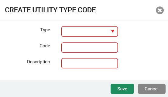
- Select the code Type, and then enter the code, up to four characters, and description in the appropriate fields. Device codes can be alphanumeric.
- Click Save to save the changes.
The codes created or edited appear in the list of selectable codes.
Delete a Device Code
- On the Utility Management (Device Management) software page, in the Code Management section, select a code to delete, and then click Delete.
- In the confirmation dialog box, click Yes to confirm the deletion.
The code is deleted and you must create the code again, if you want to reuse it.
Manage Devices
You can easily manage the data collection devices (gateways and collectors) within your utility system:
- Edit a device name.
- Build a USB
 Universal Serial Bus. An industry standard that establishes specifications for cables, connectors, and protocols for the connection, communication, and power supply between personal computers and peripheral devices. to configure a device.
 - You can also clone devices to create a new device with the same network connections and IP Internet Protocol. addresses as a device already in the system.
You can filter the grid of devices to easily search for a specific device.
Clone a Device
You can clone a device to create a second device with the same configuration as the first one. You can update most of the configuration data for the cloned device. You can clone only R900 gateway (GPV4) devices and collectors.
- On the Utility Management (Device Management) software page, in the Device Management section, click in the row of the device to clone to select it.
- Click Clone.
The system displays the device configuration window with the data from the existing device in place.
- Type the device name and ID in the appropriate fields.
- Edit other data for the new device as required.
- Click Save to create the device.
The new device displays in the Device Management list.
Add an R900® Gateway (GPV4E)
- On the Utility Management (Device Management) software page, in the Device Management section, click Create, and then click R900 Gateway (GPV4E).
The system displays the configuration window for the device type.
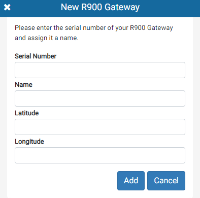
- In the Serial Number field, enter the serial number of the gateway.
The serial number is an alphanumeric value in GPV4EXXXX format that is under the FCC label on your gateway.
- In the Name field, enter a unique and descriptive name for the gateway.
- Optional: in the Latitude and Longitude fields, enter the latitude and longitude of the gateway location. Enter the latitude and longitude in decimal degrees format, with a maximum of six decimal places.
- Click Add to add the R900 gateway (GPV4E).
Neptune® 360™ displays a new record for the gateway in the in the Device Management Table. The gateway Type displays R900 Gateway (GPV4E). Now you can Configure an R900® Gateway (GPV4E) to Use Static Network Parameters.
Configure an R900® Gateway (GPV4E) to Use Static Network Parameters
By default, an R900 gateway (GPV4E) is set to acquire network settings automatically via DHCP![]() Dynamic Host Configuration Protocol, a network management protocol that automatically assigns IP addresses and other communication parameters to devices on a network. from your server, which includes the IP address, a subnet mask, a default gateway IP address, and a DNS
Dynamic Host Configuration Protocol, a network management protocol that automatically assigns IP addresses and other communication parameters to devices on a network. from your server, which includes the IP address, a subnet mask, a default gateway IP address, and a DNS![]() The standard port number for Domain Name System. The standard DNS port number is 53 for all User Datagram Protocol activities. server. Some networks may not support DHCP and some organizations may prefer to assign static network parameters to their gateways. In this case, you can configure your gateway to use static network parameters by downloading an .ini
The standard port number for Domain Name System. The standard DNS port number is 53 for all User Datagram Protocol activities. server. Some networks may not support DHCP and some organizations may prefer to assign static network parameters to their gateways. In this case, you can configure your gateway to use static network parameters by downloading an .ini![]() Initialization or configuration file used to store settings for the application. file from Neptune 360. You can download a local configuration file that contains the static network parameters for your gateway, and apply the configuration file to your gateway using an SD card.
Initialization or configuration file used to store settings for the application. file from Neptune 360. You can download a local configuration file that contains the static network parameters for your gateway, and apply the configuration file to your gateway using an SD card.
- On the Utility Management (Device Management) software page, in the Device Management section, click the device ID for the gateway you want to configure.
- Click
 .
.
- Click Configure via SD Card.
The system displays a Configure Via SD Card form.
- In the Static IP Address field on the form, enter the IP address assigned to the gateway's Ethernet interface.
You can enter either an IPv4![]() Internet Protocol version 4 or version 6 is the address of a device that accesses the internet. IPv4 is a 32 bit address and IPv6 is a 128 bit hexadecimal address. or an IPv6
Internet Protocol version 4 or version 6 is the address of a device that accesses the internet. IPv4 is a 32 bit address and IPv6 is a 128 bit hexadecimal address. or an IPv6![]() Internet Protocol version 4 or version 6 is the address of a device that accesses the internet. IPv4 is a 32 bit address and IPv6 is a 128 bit hexadecimal address. address, with a prefix length that specifies the subnet mask such as, 10.0.0.1/16 or FE80:CD00:0000:0CDE:1257:0000:211E:729C/64. For example, for 10.0.0.1/12, the prefix length 12 means that the first 12 bits of the address identify the subnet. The subnet mask is 255.240.0.0.
Internet Protocol version 4 or version 6 is the address of a device that accesses the internet. IPv4 is a 32 bit address and IPv6 is a 128 bit hexadecimal address. address, with a prefix length that specifies the subnet mask such as, 10.0.0.1/16 or FE80:CD00:0000:0CDE:1257:0000:211E:729C/64. For example, for 10.0.0.1/12, the prefix length 12 means that the first 12 bits of the address identify the subnet. The subnet mask is 255.240.0.0.
- In the Network GW IP Address field, enter the network gateway IP address, which is the network gateway (default route) IP address assigned to the gateway's Ethernet interface.
You can enter either an IPv4 or an IPv6 address like 10.0.0.1 or FE80:CD00:0000:0CDE:1257:0000:211E:729C.
- In the Domain Name Server field, enter the address of the Domain Name System server assigned to the gateway's Ethernet interface.
You can enter up to three IPv4 or IPv6 addresses in a space delimited list. For example, 10.0.0.1 10.0.0.2 FE80:CD00:0000:0CDE:1257:0000:211E:729C.
- Click Save.
- In the confirmation box, click Yes, Download the confirm the configuration.
The system generates and downloads the configuration file, which has a .ini extension.
- Save the file to your computer.
- Insert the SD card into the SD card slot of the gateway.
You can insert the card at any time before or after the gateway boots. The gateway reads the configuration file from the SD car and applies the static network parameters. The gateway displays the network parameters in the Configuration section on the window in Neptune 360, if the gateway successfully applies the changes.
Configure an R900® (GPV4E) Gateway Remotely
Neptune software administrators handle all remote configuration of R900 gateways.
Create an R900 Gateway (GPV4E) Device
- On the Utility Management (Device Management) software page, in the Device Management section, click Create, and then click R900 Gateway (GPV4E).
The system displays the Gateway Configuration window for the device type.
Select and type data in each field for the new device as required. Neptune previously recorded your gateway ID.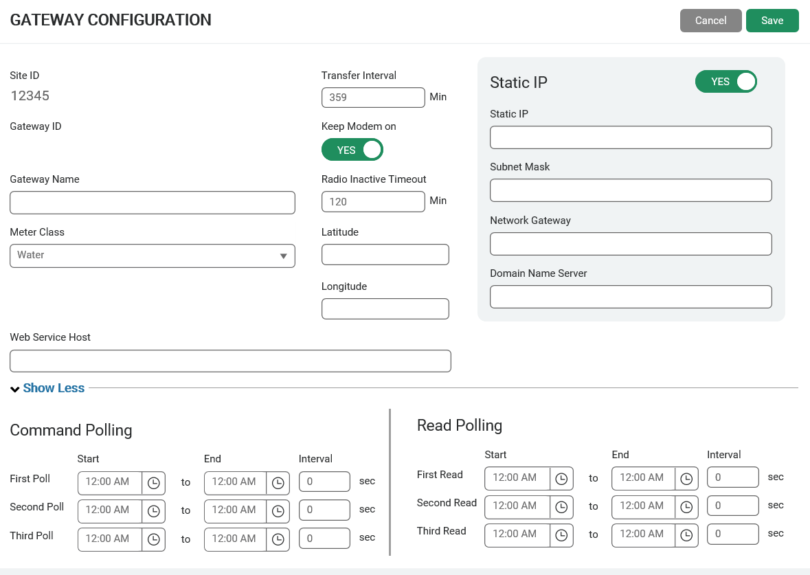
- Click Save to create the device.
The new device displays in the Device Management list.
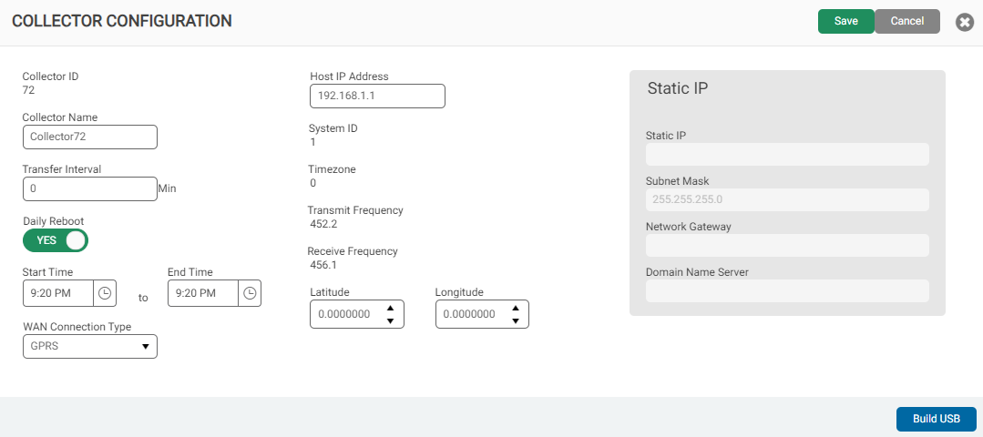
Create a Collector
- On the Utility Management (Device Management) software page, in the Device Management section, click Create, and then click Legacy Gateway as the device type to create.
The system displays the configuration window for the device type.
- Enter and select the options for the collector, as required.
- Click Save to create the device.
The new device displays in the Device Management list.
Build the USB to Configure a Collector or R900 (GPV4) Device
You can create a configuration (.cfg) file for any device in your system.
- On the Utility Management (Device Management) software page, in the Device Management section, click the Device ID of the R900 gateway (GPV4) collector device for which you want to configure a USB.
The system displays the Device Configuration window with the current configuration.
- If you are building a USB for a legacy gateway, click Edit and then go to step 3. Otherwise, go directly to step 3.
- Update the information in the window as required, and then click Build USB.
- The system creates a configuration file for the device and saves to the default location defined by the browser. See the downloaded file displayed in the bottom left corner of your window.
Edit a Device Name
Changing the name of a device does not impact its functionality.
- On the Utility Management (Device Management) software page, in the Device Management section, click
 for the device for which you want to change the name.
 - In the Edit Device dialog box, type a new name, and then click Save.
Delete a Device
Before you delete a device, make sure it is not currently used in the field.
- On the Utility Management (Device Management) software page, in the Device Management section, select the device to delete. You can filter the grid to easily identify the correct device.
- Click Delete.
- Click Delete again to confirm you want to delete the device.
The deleted device no longer displays in the Device Management list.
